How do I know if I have an air leak?
Large air leaks can be detected by vacuum symptoms: loud gurgling noise
from the foreline pump, inability of the turbo pump to reach 95% speed or, in
the case of smaller leaks, high pressure readings on the high vacuum gauge
controller.
The mass flow controller is calibrated for methane and the high vacuum gauge
controller is calibrated for nitrogen, so measurements are not accurate in
absolute terms:
Familiarize yourself with the measurements on your system under operating
conditions. Watch for changes that may indicate a vacuum or gas flow
problem.
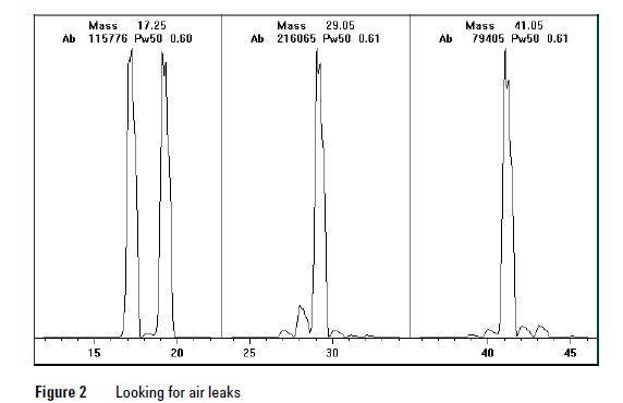
Always look for small air leaks when setting up methane flow. Run the
methane pretune, starting with a good PCI tune file (Figure 2). The abundance
of m/z 19 (protonated water) should be less than 50% of m/z 17 for acceptable
PCI performance. For NCI, the abundance of m/z 19 (protonated water)
should be less than 25% that of m/z 17. If the MSD was just pumped down, look
for the abundance of m/z 19 to be decreasing
There should not be any peak visible at m/z 32 (O2). This almost always
indicates an air leak.
Special NCI notes
Since NCI is so extremely sensitive, air leaks that are not detectable in EI or
PCI can cause sensitivity problems in NCI. To check for this kind of air leak in
NCI, inject OFN. The base peak should be at m/z 272. If the abundance of
m/z 238 is much greater than that of m/z 272, you have an air leak.
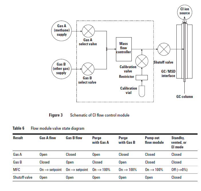
How do I find the air leak?
1 See Figure 3 and Table 6.
2 Look for the last seal that was disturbed.
• If you just pumped down the MSD, press on the sideplate to check for
proper seal. Poor alignment between the analyzer and the GC/MSD
interface seal can prevent the sideplate from sealing
• If you just replaced the reagent gas bottle or gas purifier, check the
fittings you just opened and refastened.
3 Check for tightness of seals at GC inlet and interface column nuts. Ferrules
for capillary columns often loosen after several heat cycles. Do not
overtighten the interface nut.
4 If any of the fittings inside the flow module (VCR fittings) were loosened
and then retightened, the gasket must be replaced. These gaskets are good
for one use only.
5 Remember that most small air leaks visible in CI mode are located in either
the carrier gas or reagent gas flow paths. Leaks into the analyzer chamber
are not likely to be seen in CI because of the higher pressure inside the
ionization chamber.
6 Half-split the system.
• Close valves starting at the gas select valves (Gas A , then Gas B), then
close the shutoff valve. See Figure 3 and Table 6.
• Cool and vent the MSD, remove the GC column, and cap off the interface.
If you use argon or other introduced gas to find air leaks, this does not work
well for the reagent gas flow system. It takes as long as 15 minutes for the peak
to reach the ion source if the leak is at the inlet to the flow module.